Soldering & Breadboard
|
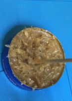
Tasked to solder 2 alligator clip wires was fairly fun. The alligator clip wire was intended to serve as a power source to the breadboard and is a great item to practice soldering with. Provided with one black and one red wire, I had to clip both rubber ends of the wire to expose the copper wire inside. I then twisted the copper wire to ensure no strand is out of place and dipped it into the flux, a gel-like substance, thinly. The flux is used to prevent the metal surfaces from re-oxidation during soldering. I then soldered the exposed copper wires using the soldering iron and solder wire silmultaneously, and here's how they turned out:
| |||||||
|
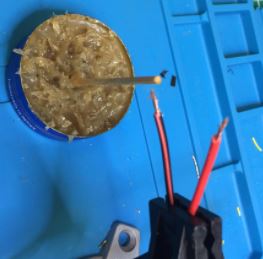
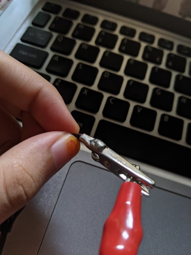
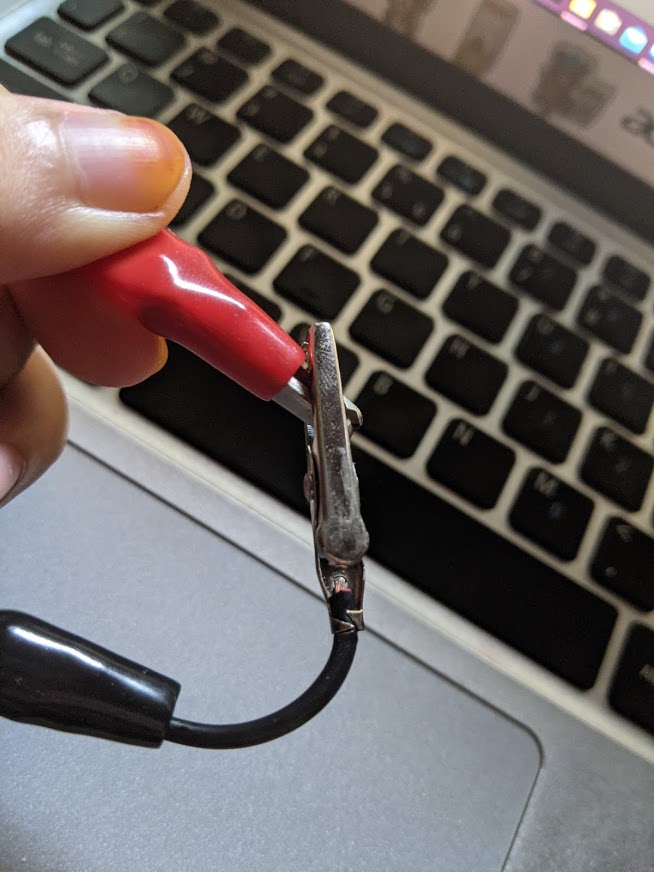
Next I put the rubber cover onto the two wires individually. This rubber cover will be used to cover the soldered part of the copper wire and the alligator clip. It will be easier to put the rubber covers into the wire first as the clip is 'V' shaped and the rubber covers openings are small at the ends. Afterwards, I slipped the soldered copper wire into the hole of the alligator clip and bent it to try and make it as flat as possible before soldering. This reduces the bulk when i push the rubber cover up. I then started to apply just a bit of flux onto the area i wanted to solder and started to solder it. | |||||||
| |
|||||||
 |
 |
||||||
|
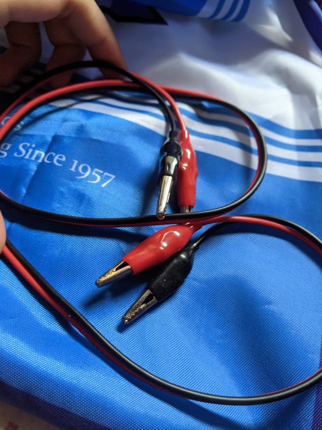
After soldering all four clips and all four exposed copper wires, they look like below. I then started to push the rubber covers up only after clipping the alligator clips onto another as it will be easier that way. Afterwards, I was done! | |||||||
| |
|||||||
 |
 |
 |
|||||
|
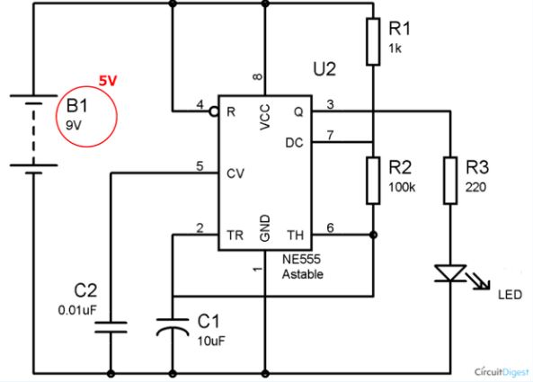
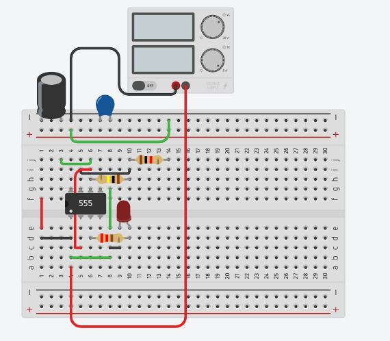
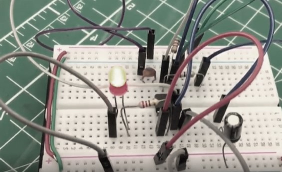
Afterwards, I did the 555 timer task. Using the TinkerCAD platform, i designed my circuit by referencing the given circuit design. Then once it worked, i implemented it onto my physical breadboard as below. | |||||||
| |
|||||||
 |
 |
 |
|||||