Arduino and Input/Output
Toggle Push Button InputFor this part, we were tasked to create a circuit which allows control for 2 LEDs using a push button. There were a series of sub-tasks to accomplish mainly: Simple LED control
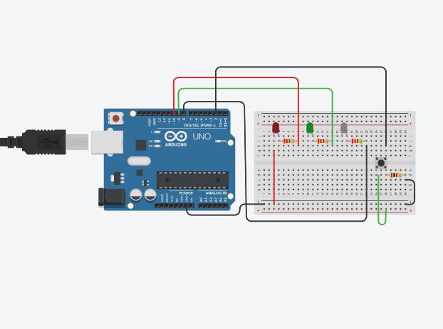
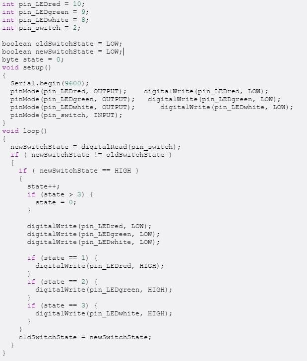
I created a circuit using Arduino first before implementing it into my physical circuit. I also generated a code that will aid in the different steps of pressing the push button. The parts needed were:
| |||||||
| |
|||||||
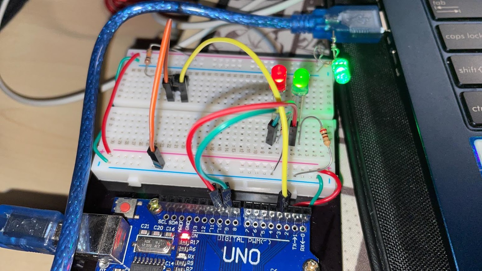
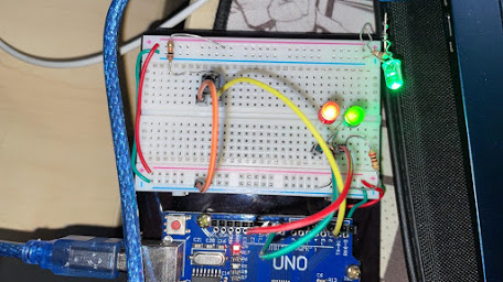
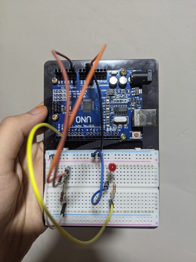
I then proceed to create the physical circuit following the one i created in TinkerCAD. Here i made some minor changes to the layout, but not obstructing its main purpose. You may change around the circuit as you please, though be careful when you are unsure as it could short circuit. |
|||||||
| |
|||||||
 |
 |
||||||
| |
|||||||
| |
|||||||
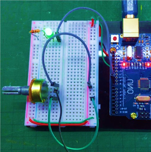
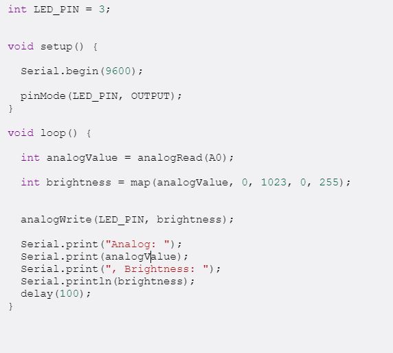
Potentiometer InputNext up is the circuit using a potentiometer to control the intensity of the light. I similarly did the circuit on TinkerCAD first and did the circuit physically on my breadboard. |
|||||||
| |
|||||||
.jpg) |
 |
 |
|||||
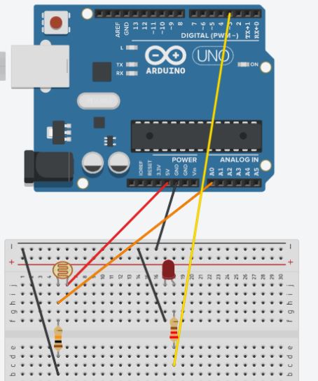
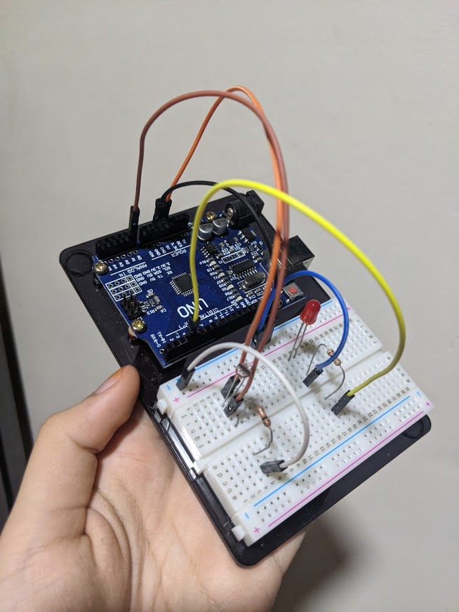
Output (LDR)An example of an output circuit is an LDR circuit. An LDR circuit depends on the light exposed to the Photo Resistor. The Photo Resistor would sense the availability of light exposed to it and if there is no light, the LED in the circuit would light up. When there is light, the LED in the circuit would not light up |
|||||||
| |
|||||||
 |
 |
 |
|||||