Puzzle Box
|
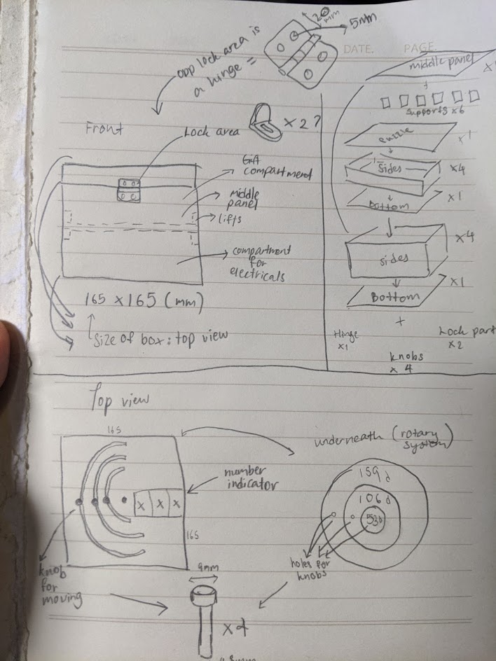
For this module project, I intend to build a puzzle box that can be used for gifting purposes, versatile for any occassion. It is a simple yet thoughtful product for those who likes mystery puzzles. I obtained the idea from a youtube video called "How I proposed: fairytale story with puzzles and secret at end" showcasing a proposal puzzle book, that has 5 pages with mechanisms for the receiver to work and solve. Though I wanted to replicate a similar one, it was not possible due to deadlines, thus i simplified the idea into a puzzle box instead, holding 1 puzzle page at hand. With the replacement of the remaining 4 pages with a bigger, hollow box, i would be able to store the electrical components and a gift, which would not be possible if i had followed the initial plan. I also created a rough sketch of how my product should be and should have. My presentation slide is as so: My presentation
PARTS for project, all 3mm in thickness(Starting from base to top, to other components):
The Autocad file and coding for the circuit is here for your reference:
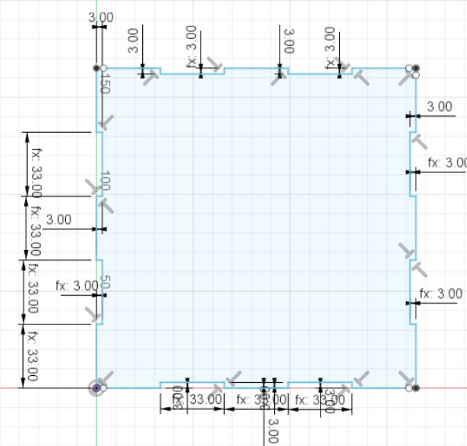
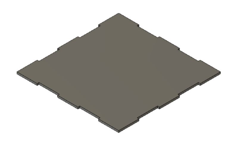
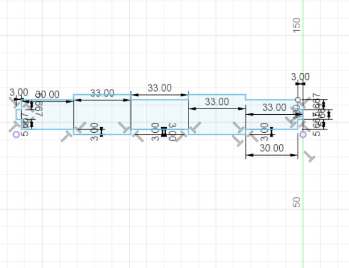
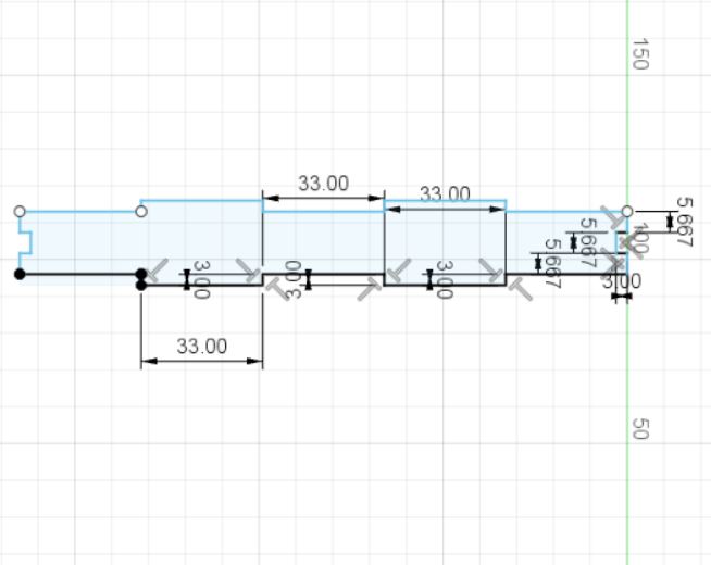
Creating the box/parts using Autodesk Fusion 360:Create a component and name it as bottom for box bottom (1). (For every part to be created, select "New Component". Ensure that the whole base design is selected and not just one part when creating the following parts.) Once done, extrude the piece at 3mm. Press enter and the bottom piece is done! Now, to create the following parts, select the entire project (the one named as the file name on the top left side NOT the part we have just created). Once selected, create "New component". This will indicate the next part to be made. Rename every part to the respective side or object of the project. This way, you wouldn't be confused. Create the next part, either left or right and input the above dimensions. This can be the left side. Once done, repeat the extrusion. To save time from creating the right side, create a midplane. This is done by: Contruct > Midplane > (select the left part face and the bottom right (side) face. Once the plane is created, we may go to Create > Mirror > (select component), Object:(select the left component),Mirror Plane(the plane we have just generated). The right side then will be generated as a component. Do the same for the Front side for the Back side. Right = Left, and Front = Back. |
||||||
| |
||||||
 |
.jpg) |
.jpg) |
||||
| |
||||||
 |
.jpg) |
.jpg) |
||||
| |
||||||
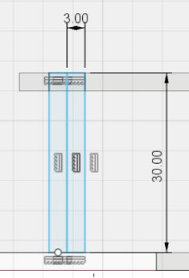
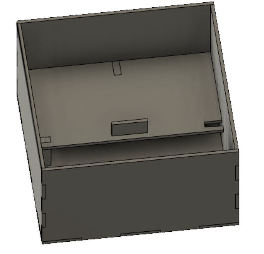
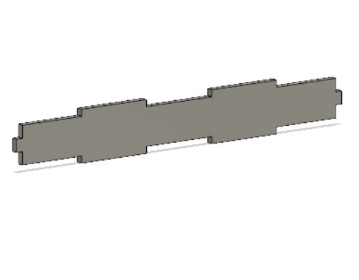
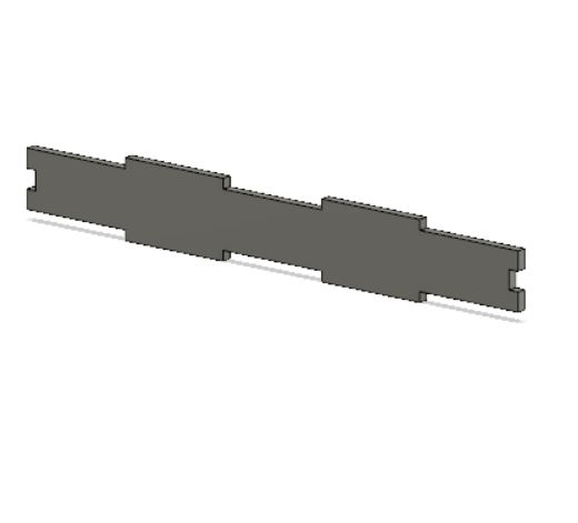
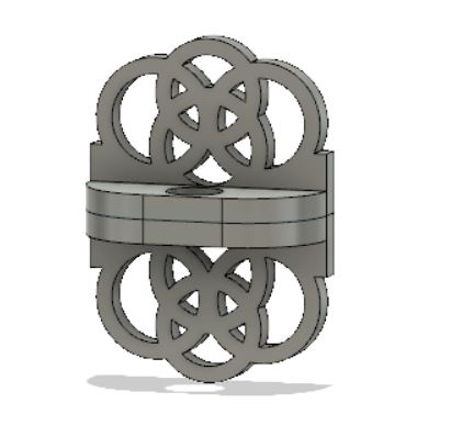
Combine the parts to create a box with no lid. Create the middle panel as per the dimensions. Afterwards, create the side supports and the lifting support. Combine these parts. The supports have 2 pieces attached for the bottom portion of the middle panel. The other side of the middle panel is left empty for the usb wire. Once combined, they will consist of: the bottom panel, side panels, middle panel and supports. |
||||||
| |
||||||
 |
 |
 |
||||
| |
||||||
 |
 |
|||||
| |
||||||
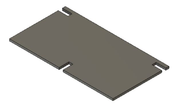
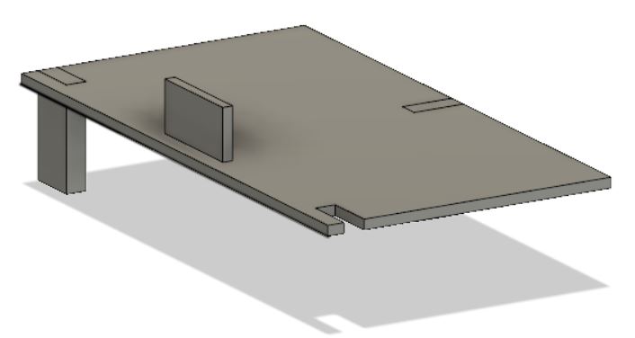
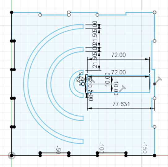
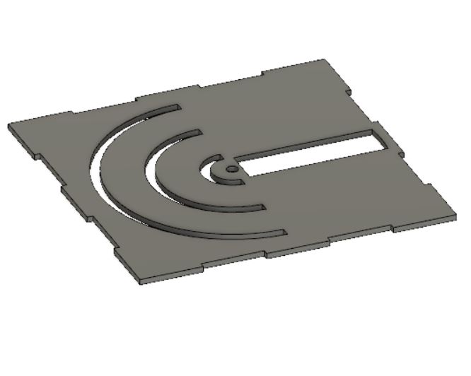
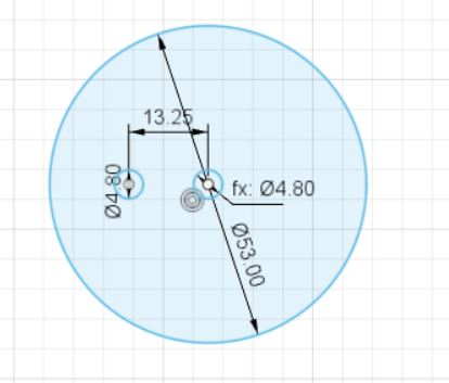
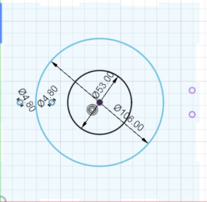
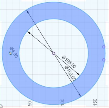
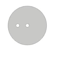
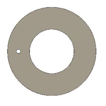
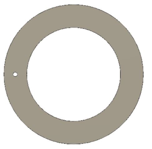
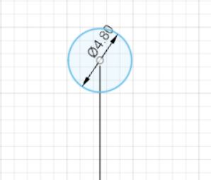
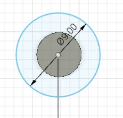
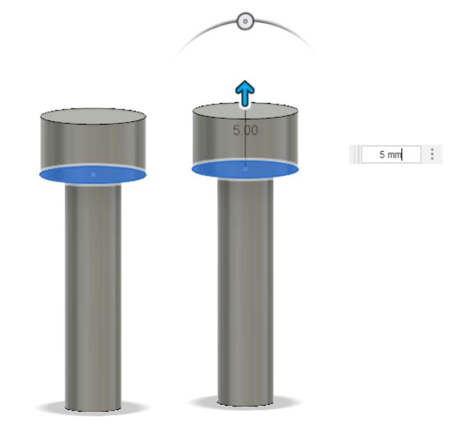
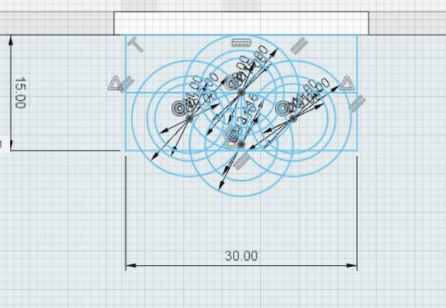
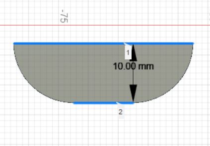
The next part would be to start the bottom panel of the puzzle box. Follow the dimensions as per below and follow the same steps as the previously made box. The puzzle bottom panel dimensions are the same as the previous bottom panel. Then, create the top puzzle box piece using the dimensions as below. Now we have the full bottom box and the top puzzle box done. We then create the rotary pieces. |
||||||
| |
||||||
 |
 |
 |
||||
| |
||||||
 |
 |
 |
||||
| |
||||||
 |
 |
 |
||||
 |
 |
 |
||||
| |
||||||
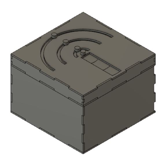
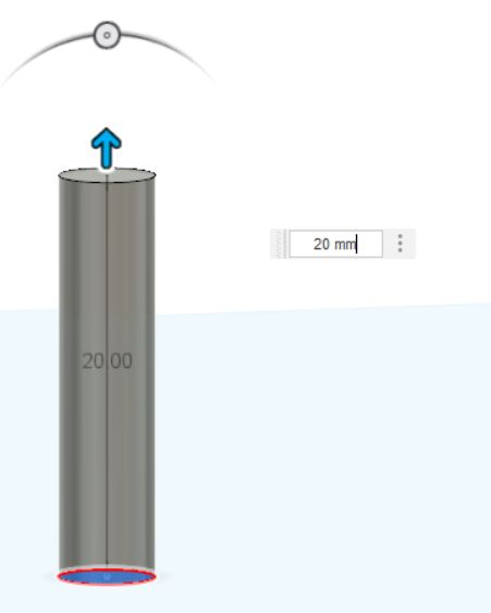
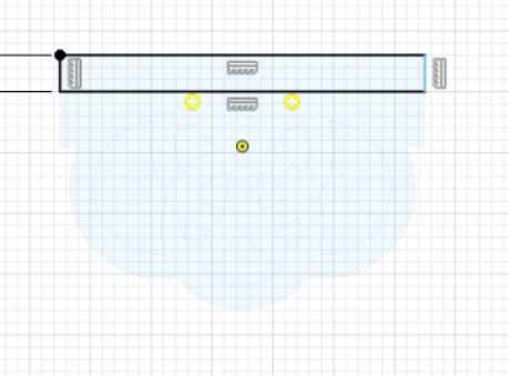
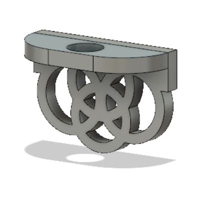
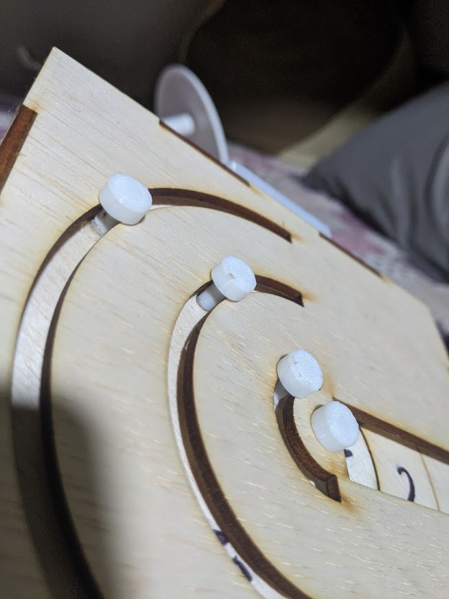
| We then create the knobs. We create a sketch on the bottom puzzle piece, following the location of the holes from the rotary pieces. Once the circles are sketched, we extrude them up until the top flat surface of the puzzle box. Then we create another sketch using the centre of the previously sketched circle to create the upper piece. Extrude this part too. Now with all the parts combined, they should look like the picture below. | ||||||
| |
||||||
 |
 |
 |
||||
| |
||||||
 |
 |
|||||
| |
||||||
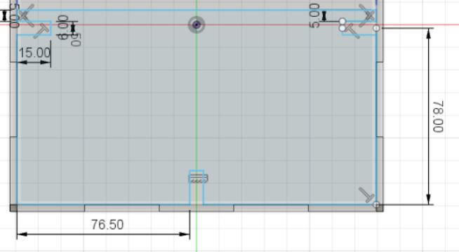
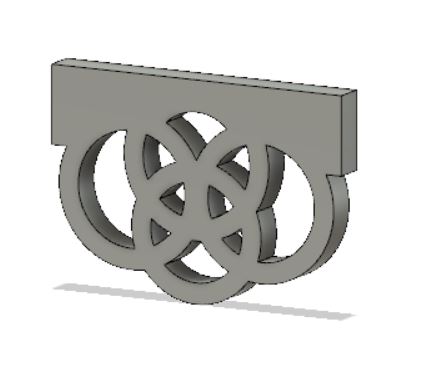
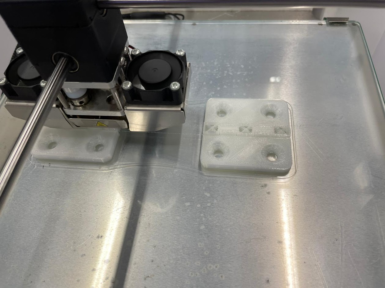
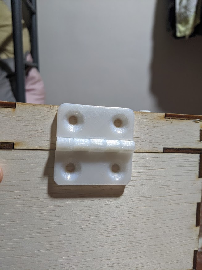
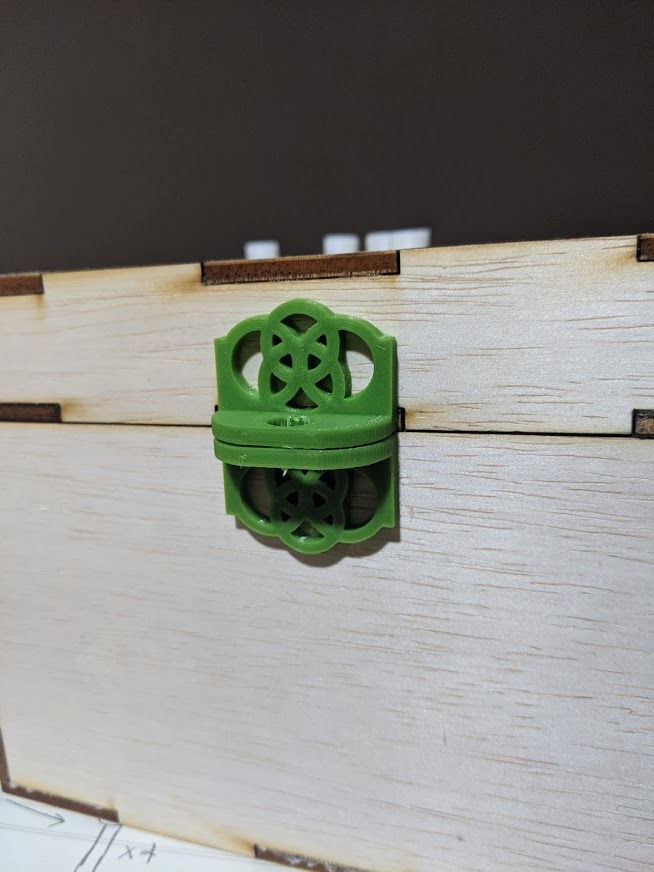
| Now we move on forward to the lock parts, hinge and we can proceed to the electronics part. For the lock, using the bottom front piece as reference as where to start, create the piece using below dimensions. The lock is separated into two parts: the lock area and the design area. Create the design one first and the lock area second. For the lock area, create the hole: 7mm, depth of 3mm, and fillet the sides 10mm. These are to be combined. After, create a mid plane using the top part of the lock area and the bottom of the bottom puzzle panel as reference. Mirror the object by selecting the lock as a whole and choosing the midplane we have just created. I then used an online file from Cults3d for the hinge. The hinge, lock part and knobs was done using 3d printing. I simply exported the objects as an stl file and brought it over to my Ultimaker Cura app for 3d printing. |
||||||
| |
||||||
 |
 |
 |
||||
| |
||||||
 |
 |
 |
||||
| |
||||||
 |
 |
 |
||||
| |
||||||
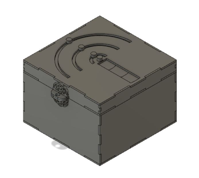
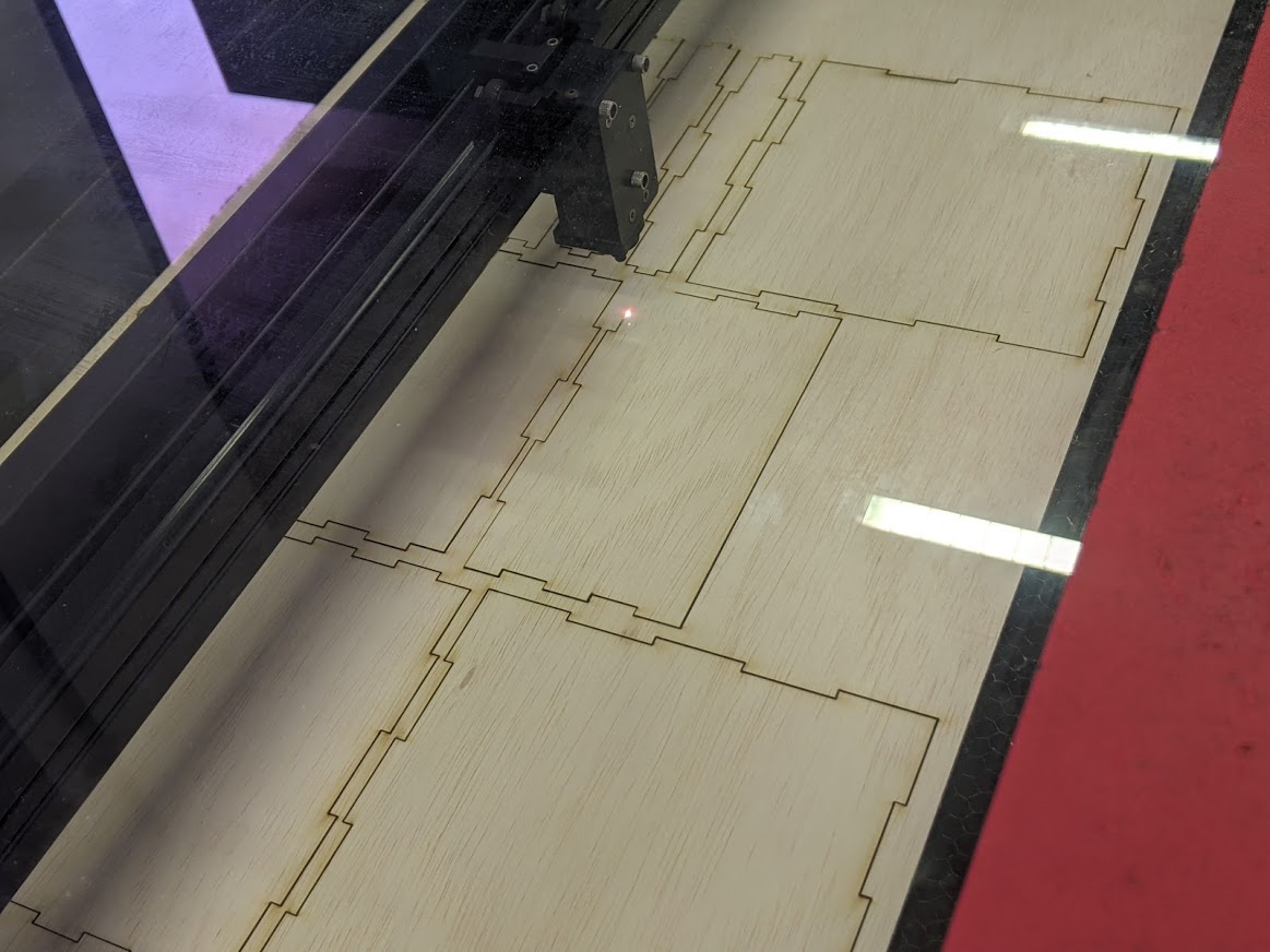
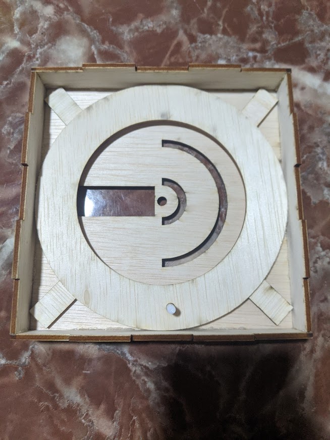
| I then proceeded to laser cut my box pieces by exporting the sketches of each part as dxf and combining them together in LIBRECAD, and then proceeded to assemble them with the 3d pieces. Here are some pictures I took. |
||||||
| |
||||||
 |
 |
 |
||||
| |
||||||
 |
 |
 |
||||
| |
||||||
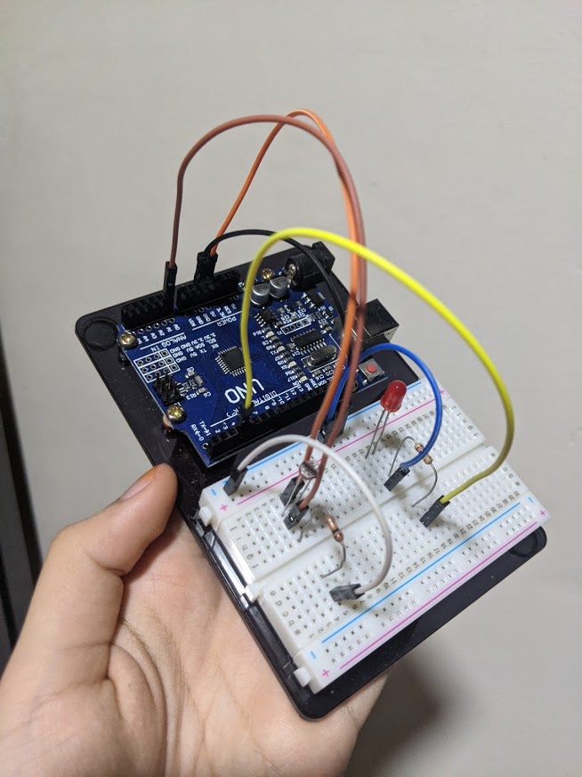
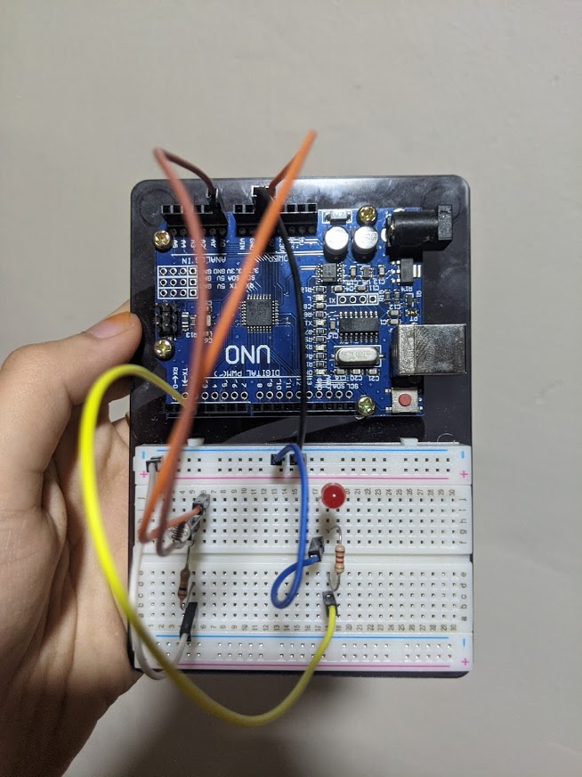
| Last but not least, I generated a reverse LDR circuit so that when the box is closed, the led will not light up, and when the box is opened, the led will light up. This is how the circuit is set up: |
||||||
| |
||||||
 |
 |
|||||
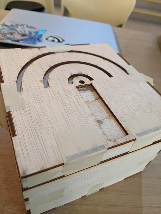
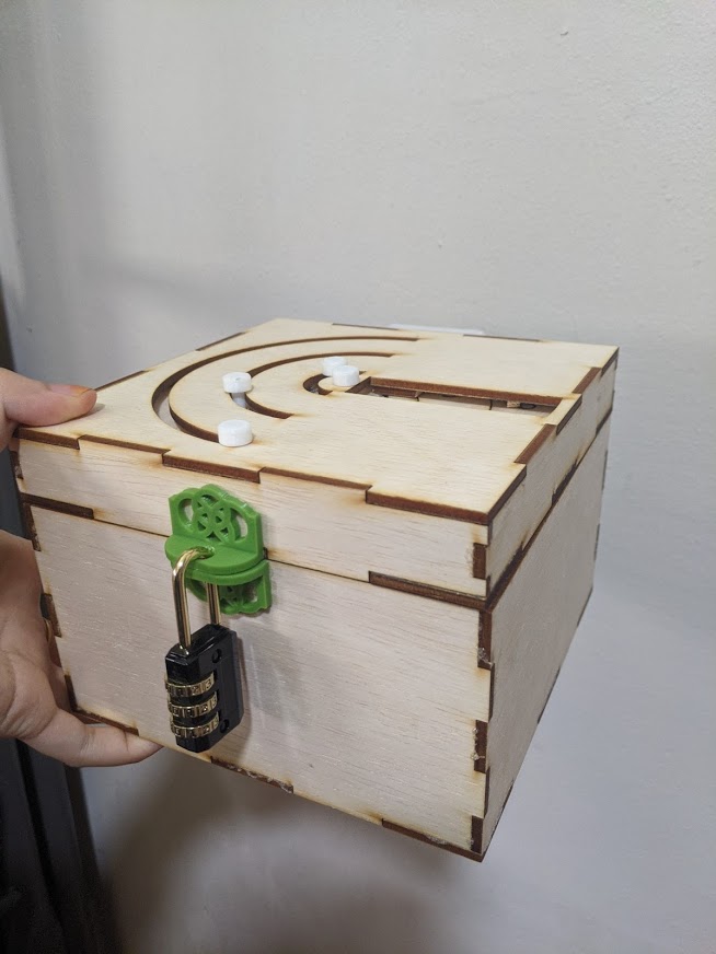
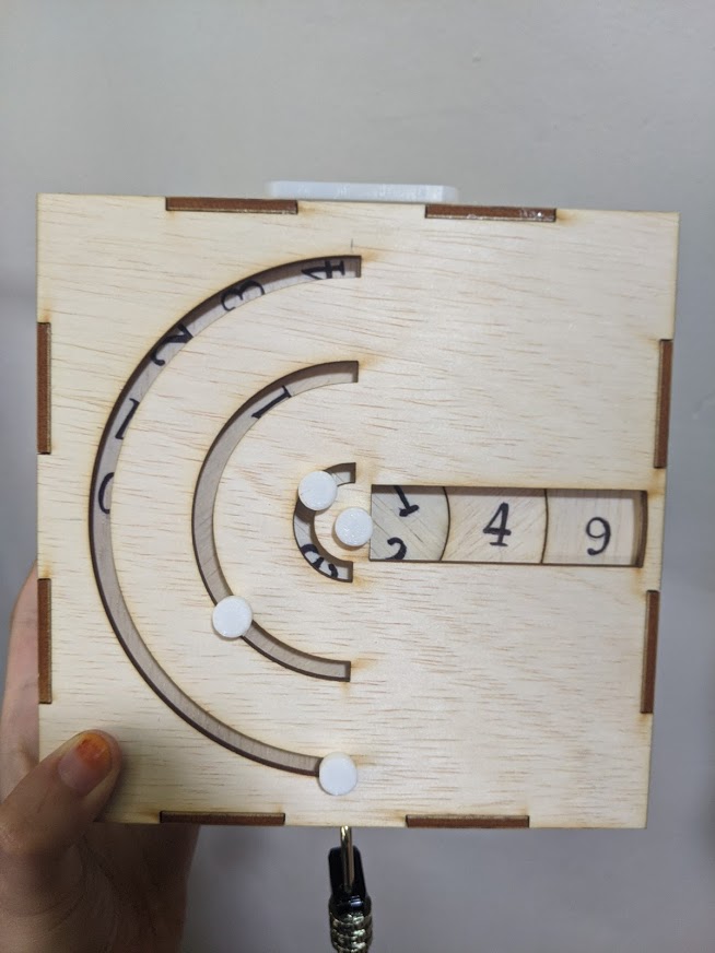
| And the end product is this! My video for how the box works is here: project 2021. shaza |
||||||
| |
||||||
 |
 |
|||||
|
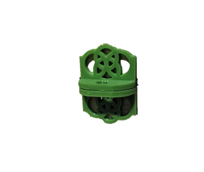
What was completed: I have managed to complete the lasercutting for the box itself, the 3d printing for the hinge, lock and knobs, and even the circuit itself which i struggled with initially. The box tabs managed to fit one another though there were some gaps, the 3d printing took a second time before it worked out as i forgot to create a support, and the circuit managed to work after a few trials. |
||||||
|
What needs to be done further: I wished that i had planned my parts properly as i realised at a certain point, i do have excess material. However, in the end, i managed to use the excess material for some parts like the rotary system which i forgot to create supports for. I also realised that i should check on the required materials beforehand and plan my box according to the resources provided. At last minute, i decided to laser cut some numbers for the box. However, due to time constraint and last minute planning, the numbers turned out fragile and unusable, therefore I had to write down the numbers using a marker in the end. However, despite the lack of careful planning, i managed to complete my project in time! |
||||||
| |
||||||
| |
||||||